Modding my Monotron Delay

Monotron Mod

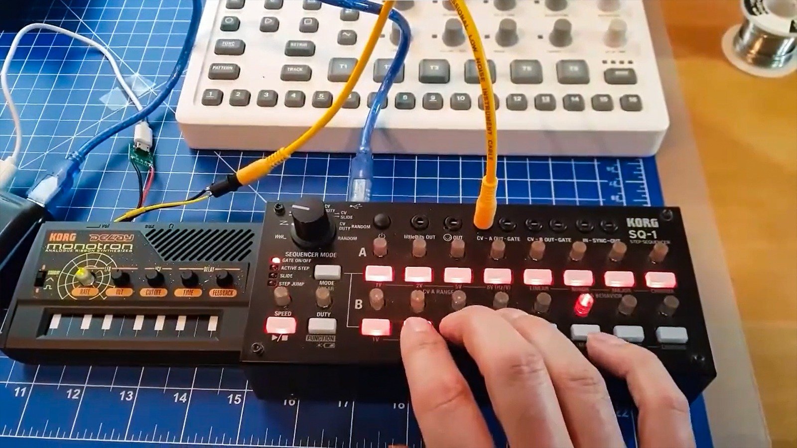
I made a first attempt at adding CV in and an external power supply to a Korg Monotron Delay:

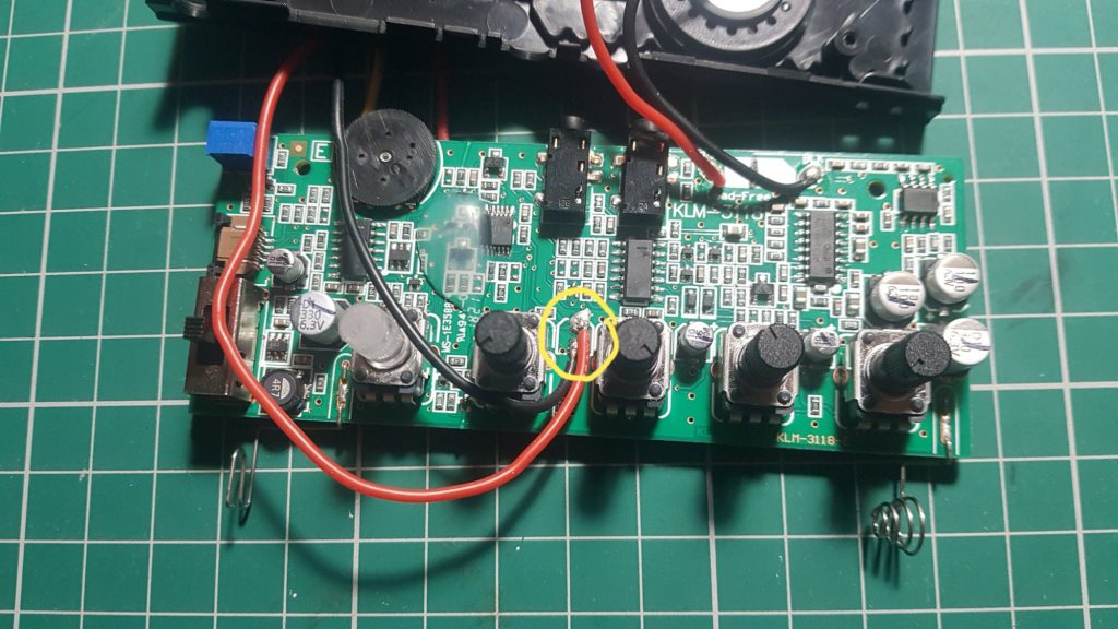
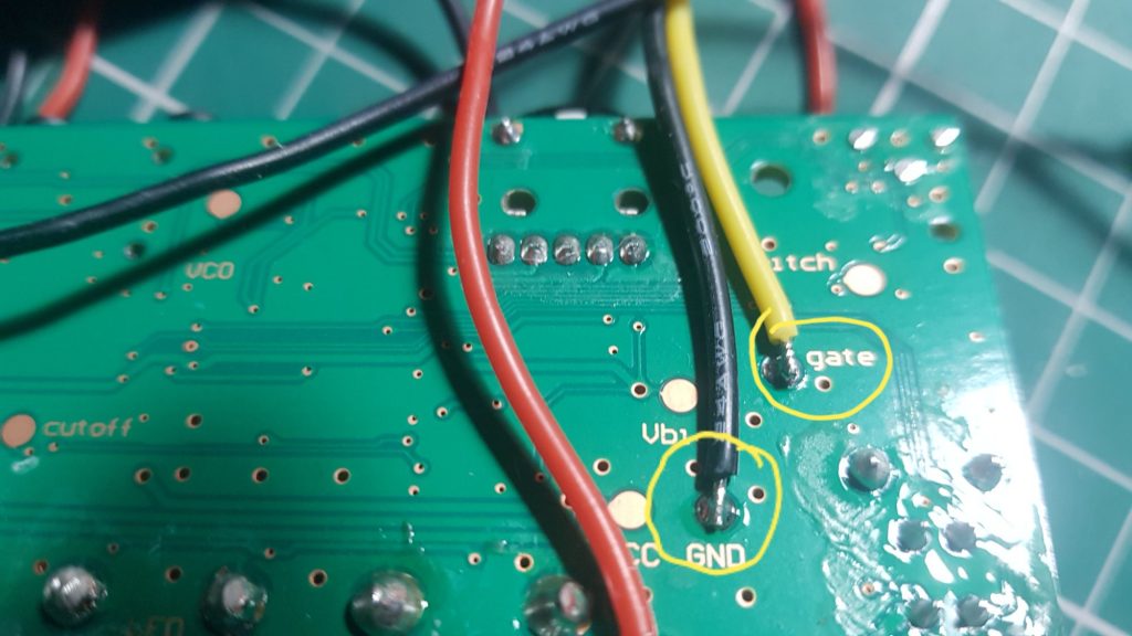
For the power I simply used an external power bank and connected 5V and GND to the respective pins on the Monotron.

5v and GND on the Monotron Delay

The 5V CV signal from the Korg SQ-1 goes into the gate pad on the Monotron. It kind of works, but tuning is quite tempera(ture)mental.

GND and gate pads on the Monotron Delay

Apart from temperature the pitch is directly dependent on the Monotron’s supply voltage, so I would either need to step down the USB voltage to ~3V and make use of the boost converter that is built into the Monotron to get 5V, or use a higher voltage power supply and regulate it down. Any idea what’s better?🤔

A second CV out for the Raspberry Pi Pico MIDI to CV converter

This entry is part 2 of 2 in the series Raspberry Pi Pico as MIDI to CV converter

In the first part of the series we built a MIDI to CV converter using MicroPython on the Raspberry Pi Pico. Check it out here if you haven’t done so already.

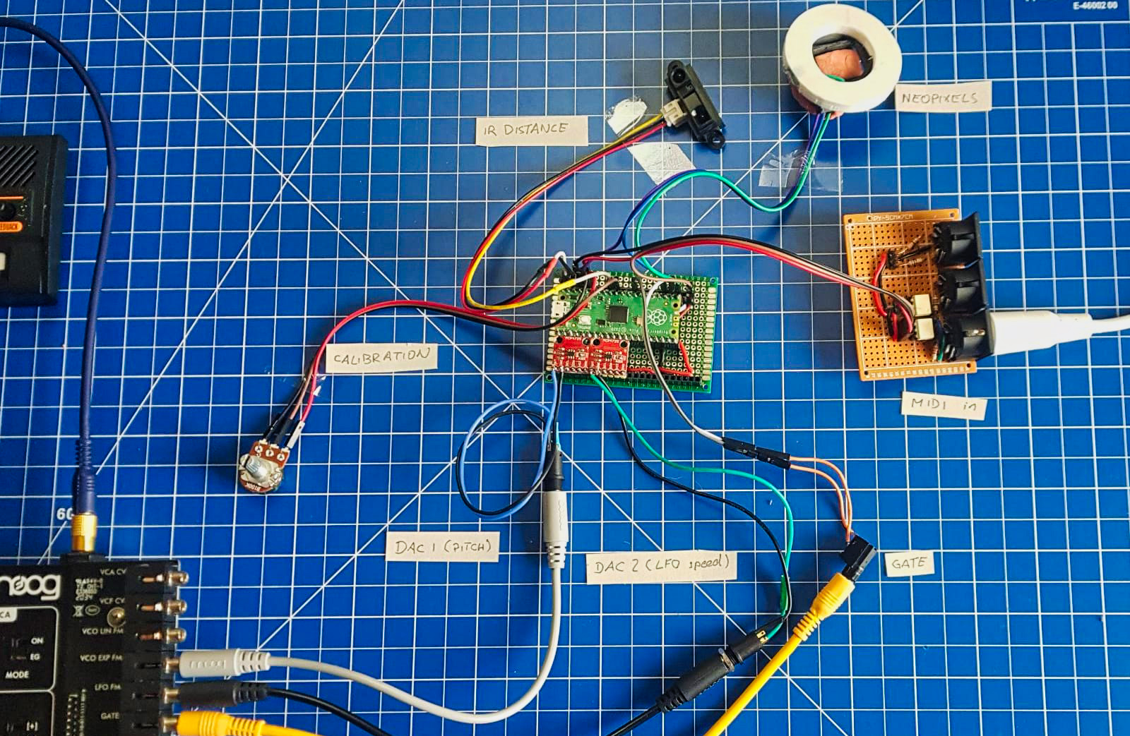
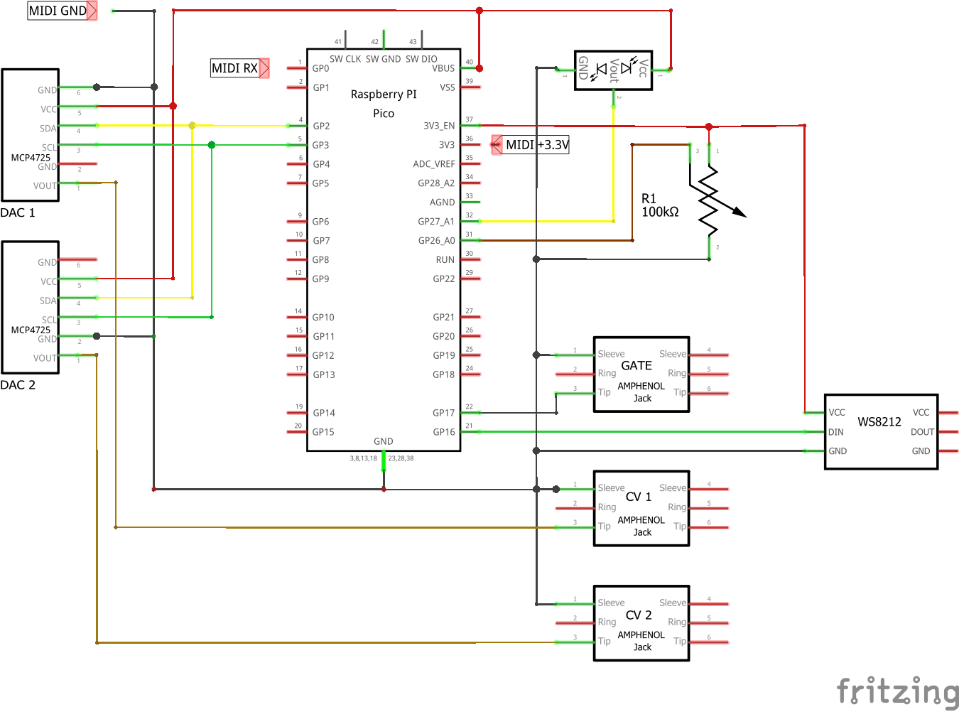
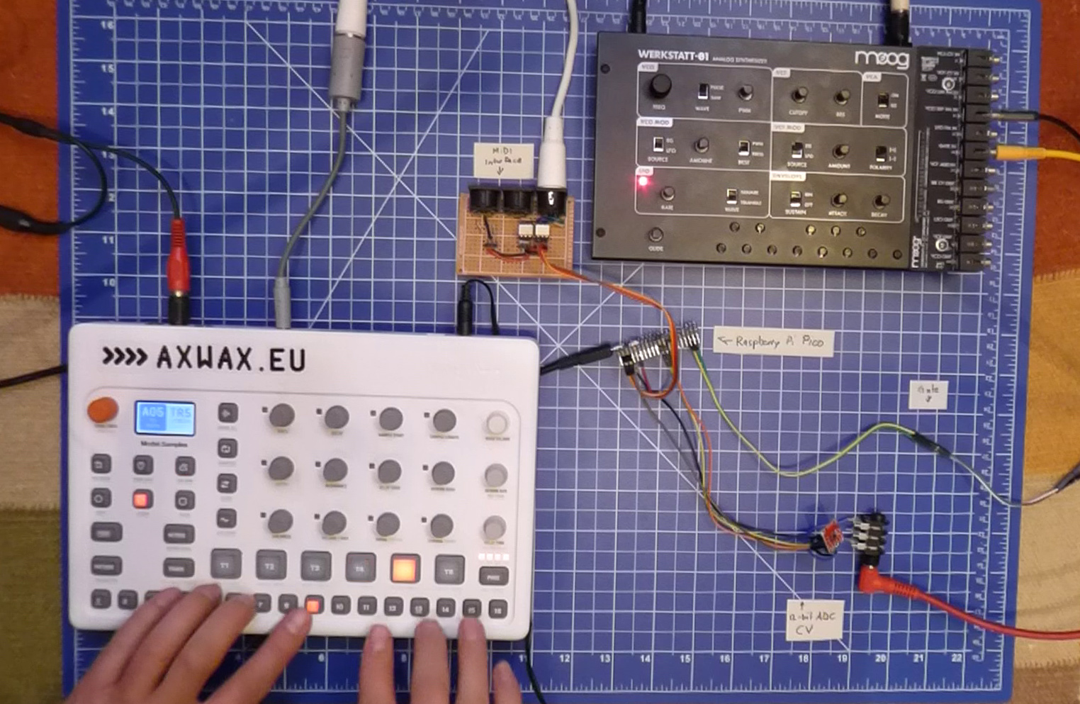
This time we’ll add a second CV output, as well as a distance sensor as a modulation source and a Neopixel ring to visualise its output.

The Set Up

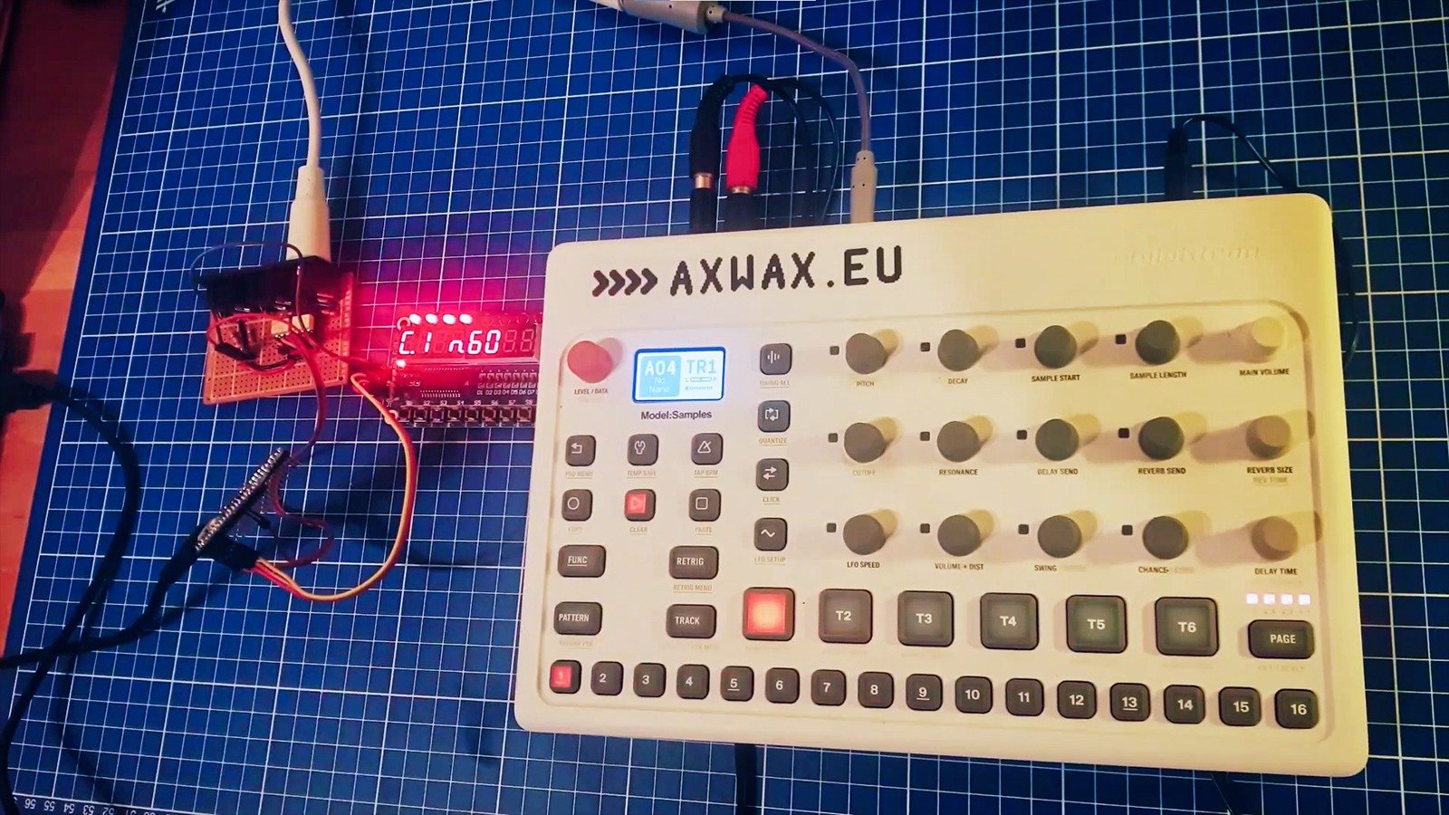
In the above video the Elektron Model:Samples is set up to generate MIDI notes on track 6, which are sent to the MIDI input on the Pico. This generates a gate signal and pitch voltage (on CV1) for the Moog Werkstatt-01.

The distance sensor’s analogue output is visualised by the Neopixel ring as well as sent to CV2, which I have connected to the Werkstatt’s LFO FM input. This allows me to control the speed of the LFO, which is in turn modulating the cutoff frequency of the bassline. Wobble ensues…

Finally, the output of the Werkstatt goes to a Korg Monotron Delay, which is used to further filter the bassline and to add a touch of delay.
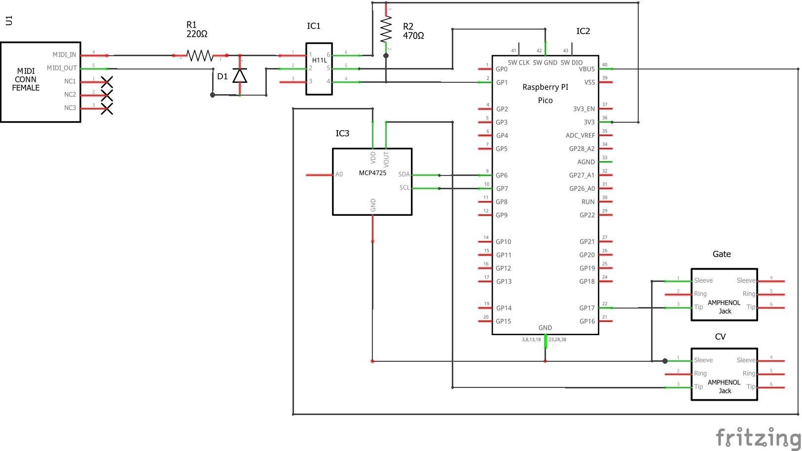
The Hardware

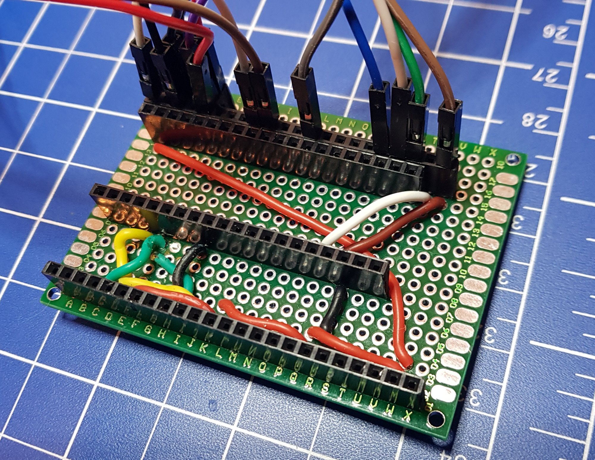
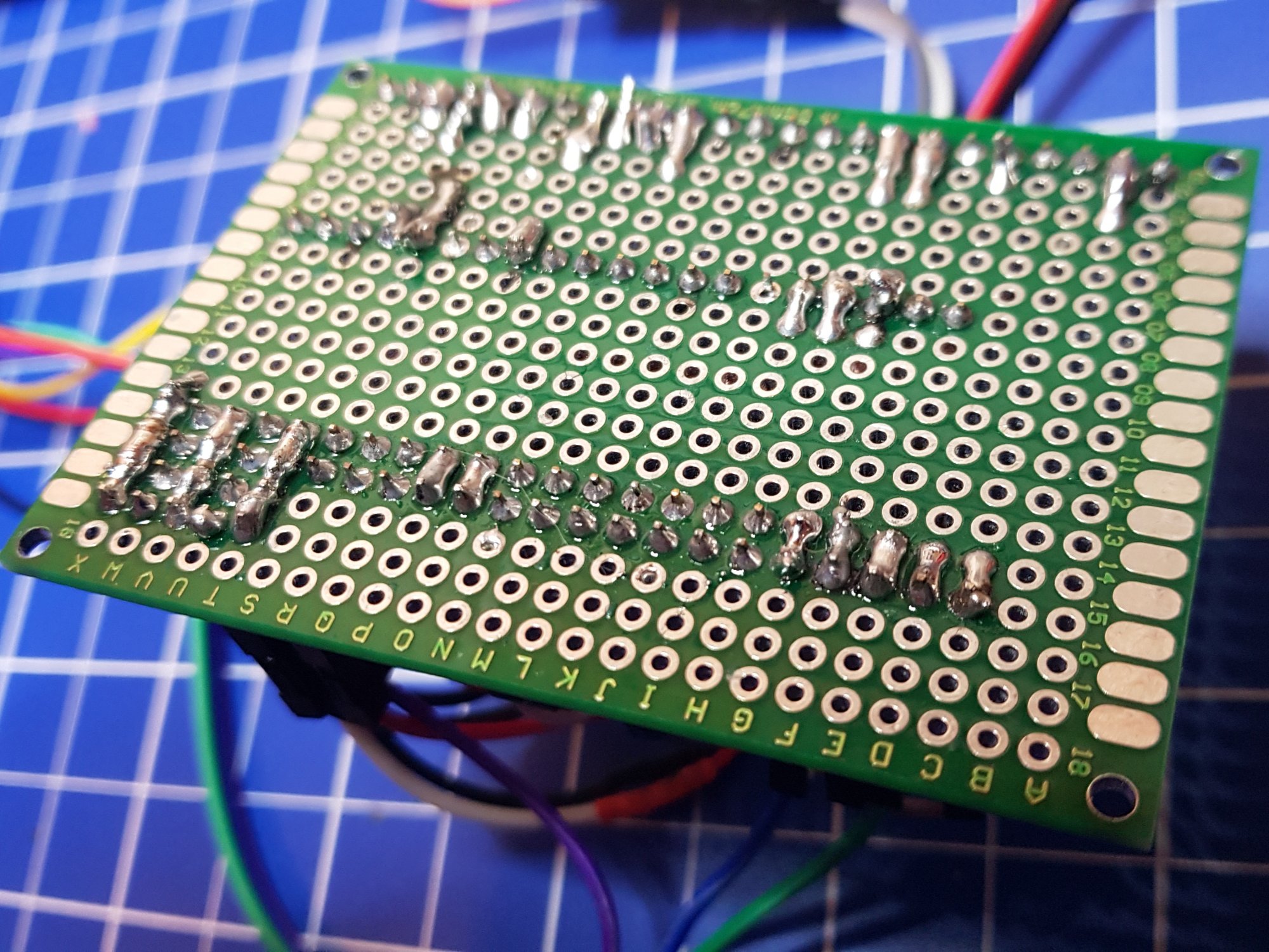
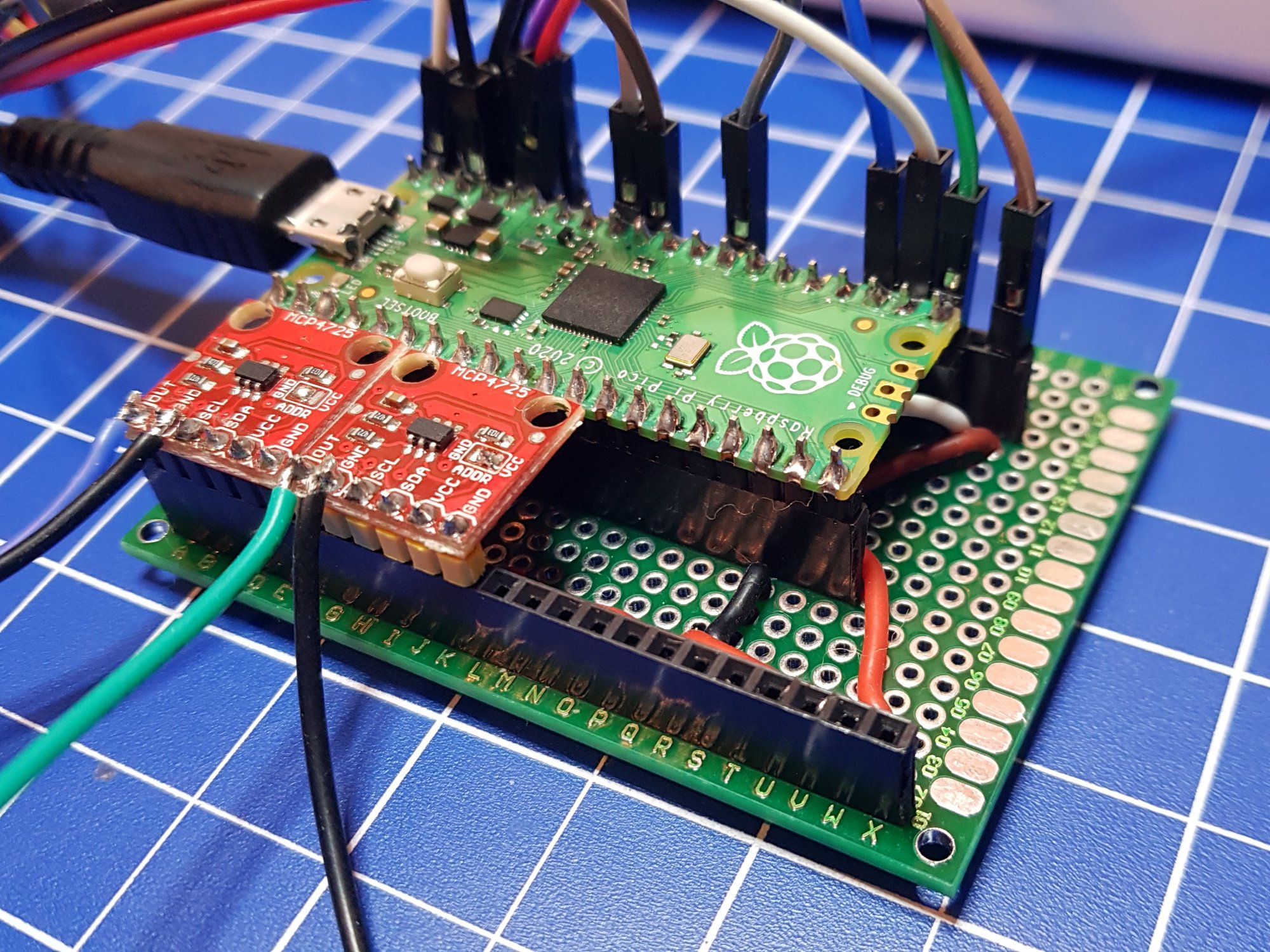
Given the multitude of in- and outputs I decided to make a semi-permanent perfboard setup with headers for the Raspberry Pi Pico and the two MCP4725 DACs.

Since space was a bit too tight for an onboard MIDI socket I am using an external daughter board, connected via jumper wires, as are the calibration pot, distance sensor, gate output and Neopixel ring.

I have added a calibration pot to the setup, as the DACs’ output voltages are directly related to VBUS (i.e. the voltage of the USB supply), which is currently used as their reference voltage. In a future revision I may add a voltage regulator to power the project with a more stable 5v.

The two DACs are connected to I2C1 on the Pico and have the addresses 0x62 and 0x63 (by soldering a jumper on one the boards). For now I simply soldered a 3.5mm jack socket to the VOUT and GND pins of each of the DACs. Eventually I may add another header on the perfboard instead.

The eagle-eyed will have spotted that there are headers (and some of the wiring) for two more DAC modules to create a possible 4CV outputs. In order to use these a second I2C bus will be needed (I2C0 on the Pico).

BOM

  • Raspberry Pi Pico
  • A 3.3V MIDI interface, such as the one we built in part 1
  • 2x MCP4725 DAC module
  • Sharp GP2Y0A21YK0F infrared distance sensor
  • 100k potentiometer
  • 16 Neopixel ring
  • 3x 3.5mm jack sockets
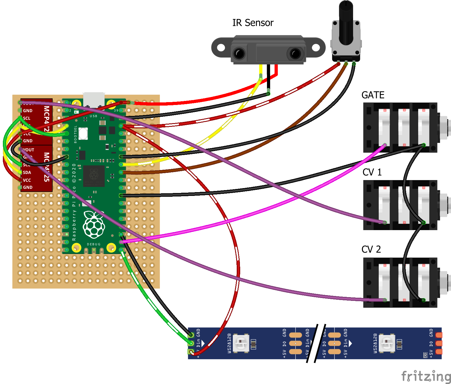
Circuit Diagram

The Code

The code is written in MicroPython. Its external dependencies are:

I have set up the functions polling the calibration pot and distance sensor ADCs to be called by a timer each, running every 100ms and 50ms respectively. For now these are just arbitrary numbers that seemed to work ok and hopefully leave enough clock cycles for the midi note commands to be tight.

The calibration pot is set up to fine-tune the expected reference voltage, from 4.5V to 5.5V to compensate for slightly different input voltages (for example, my PC’s USB port only delivers around 4.95V, whereas my phone charger outputs 5.1V).

# A second CV out for the Raspberry Pi Pico MIDI to CV converter by @AxWax
#
# Demo: https://www.youtube.com/watch?v=aGfQHL1jU4I
#
# This is heavily based on and requires
# the SimpleMIDIDecoder library by @diyelectromusic, which can be found at
# https://diyelectromusic.wordpress.com/2021/06/13/raspberry-pi-pico-midi-channel-router/
#
# The NeoPixel code requires the pi_pico_neopixel library by Blaž Rolih
# which can be found at https://github.com/blaz-r/pi_pico_neopixel
#
#
# Wiring:
# serial midi input: GP13 (UART0 RX)
# neopixels: GP16, GND, 3.3v
# gate output: GP17
# calibration pot: GP26 (A0), GND, 3.3v
# distance sensor: GP27 (A1), 3.3V
#
# MCP4725 (CV1&2) Pico
# GND: GND
# VCC: VBUS (5V)
# SDA: GP2
# SCL: GP3
# VOUT: CV output to synth
import machine
import time
import ustruct
import SimpleMIDIDecoder
from neopixel import Neopixel
# set up Neopixel ring
neopixel_count = 16
neopixel_pin = 16
strip = Neopixel(neopixel_count, 0, neopixel_pin, "GRB")
black = (0, 0, 0)
yellow = (255, 100, 0)
green = (0, 255, 0)
strip.brightness(50)
strip.fill(black)
strip.show()
# set up global variables
calibration = 0 # calibration offset for reference voltage
lowest_note = 40 # which MIDI note number corresponds to 0V CV
old_num_pixels = 0 # previous number of neopixels shown
# set up analogue inputs
analog0_value = machine.ADC(26)
analog1_value = machine.ADC(27)
analog2_value = machine.ADC(28)
# set up gate pin
gate = machine.Pin(17, machine.Pin.OUT)
gate.value(0)
# set up I2C bus 1
sda=machine.Pin(2)
scl=machine.Pin(3)
i2c = machine.I2C(1, scl=scl, sda=sda, freq=400000)
# initialise serial MIDI ports
uart = machine.UART(0,31250,tx=machine.Pin(12),rx=machine.Pin(13)) # UART0 on pins 12,13
# timer callback functions:
# calibration
def check_calibration_pot(t):
global calibration
calibration = analog0_value.read_u16()
# distance sensor
def check_distance_sensor(t):
distance = analog1_value.read_u16() / 16
writeToDac(int(distance),0x63)
#convert to number from 0 – 16
numLEDs = 16 – int(distance / 256)
neopixelDraw(numLEDs, 10)
# set up timers
distance_timer = machine.Timer()
distance_timer.init (period = 50, mode = machine.Timer.PERIODIC, callback = check_distance_sensor)
calibration_timer = machine.Timer()
calibration_timer.init (period = 100, mode = machine.Timer.PERIODIC, callback = check_calibration_pot)
# draw to neopixel ring
def neopixelDraw (num_pixels, bright):
global old_num_pixels
strip.brightness(bright)
# only redraw if the value has changed
if(num_pixels == old_num_pixels or num_pixels > neopixel_count):
return
old_num_pixels = num_pixels
# draw the pixels
strip.fill(black)
if (num_pixels == 1):
strip.set_pixel(0,green)
elif (num_pixels > 1):
strip.set_pixel_line_gradient(0, num_pixels-1, green, yellow)
strip.show()
# DAC function
def writeToDac(value,addr):
buf=bytearray(2)
buf[0]=(value >> 8) & 0xFF
buf[1]=value & 0xFF
i2c.writeto(addr,buf)
# Calculate the control voltage
def noteToVoltage(note):
reference_voltage = (4.5 + (calibration / 65536)) # from 4.5V to 5.5V
mv = 4096 / reference_voltage / 1000 # value for one mV
semitone = 83.33 * mv # one semitone is 1V/12 = 83.33mV
dacV = int((note-lowest_note)*semitone)
return dacV
# output control voltage for note on CV1
def playNote(note):
dacV = noteToVoltage(note)
writeToDac(dacV,0x62)
return dacV
# MIDI callback routines
def doMidiNoteOn(ch, cmd, note, vel):
dacV = playNote(note)
gate.value(1)
def doMidiNoteOff(ch, cmd, note, vel):
gate.value(0)
# initialise MIDI decoder and set up callbacks
md = SimpleMIDIDecoder.SimpleMIDIDecoder()
md.cbNoteOn (doMidiNoteOn)
md.cbNoteOff (doMidiNoteOff)
# the loop
while True:
# Check for MIDI messages
if (uart.any()):
md.read(uart.read(1)[0])

The Future

Things I’d like to try next:

  • Add two more DACs to I2C0 to have 4 CV outputs in total.
  • MIDI CC control for the DACs.
  • Software-based LFO and/or envelope generator.
  • Pitch bend functionality.

Raspberry Pi Pico as MIDI to CV converter

This entry is part 1 of 2 in the series Raspberry Pi Pico as MIDI to CV converter

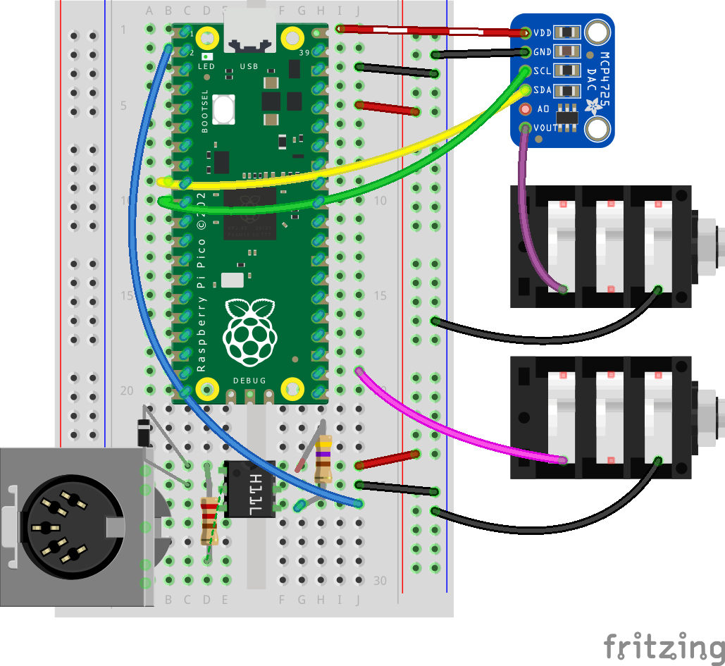
I’ve been toying with the idea of building a MIDI to CV converter for at least a decade. Now I’ve finally had a go using MicroPython on the Raspberry Pi Pico.

Here’s how I managed to control my Moog Werkstatt-01 over MIDI using the Pico, a handful of components and a MCP4725 12-bit DAC:

The Hardware

BOM

  • Raspberry Pi Pico
  • HC11L optocoupler
  • 220Ω Resistor
  • 470Ω Resistor
  • small signal diode (eg 1N914)
  • MCP4725 module

Circuit Diagram

The Code

The code is written in Micropython. Its only external dependency is the SimpleMIDIDecoder class by @diyelectromusic. You can download the latest version on GitHub here: SimpleMIDIDecoder.py.

# MIDI to CV converter for Raspberry Pi Pico and MCP4725 DAC by @AxWax
#
# Demo: https://www.youtube.com/watch?v=aGfQHL1jU4I
#
# This is heavily based on and requires
# the SimpleMIDIDecoder library by @diyelectromusic, which can be found at
# https://diyelectromusic.wordpress.com/2021/06/13/raspberry-pi-pico-midi-channel-router/
#
#
# Wiring:
# serial midi input on GP1 (UART0 RX)
# gate output: GP17
#
# MCP4725 Pico
# GND GND
# VCC VBUS (5V)
# SDA GP6
# SCL GP7
# VOUT is the CV output
import machine
import time
import ustruct
import SimpleMIDIDecoder
# which MIDI note number corresponds to 0V CV
lowest_note = 40;
# create gate pin
gate = machine.Pin(17, machine.Pin.OUT)
gate.value(0)
#create an I2C bus
sda=machine.Pin(6)
scl=machine.Pin(7)
i2c = machine.I2C(1, scl=scl, sda=sda, freq=400000)
# calculate 1mV: steps / max V / 1000
mv = 4096 / 5.1 / 1000
# calculate mV per semitone
semitone = 83.33 * mv
# DAC function
def writeToDac(value):
buf=bytearray(2)
buf[0]=(value >> 8) & 0xFF
buf[1]=value & 0xFF
i2c.writeto(0x62,buf)
# Initialise the serial MIDI handling
uart = machine.UART(0,31250)
# MIDI callback routines
def doMidiNoteOn(ch, cmd, note, vel):
global semitone
writeToDac(int((notelowest_note)*semitone))
gate.value(1)
def doMidiNoteOff(ch, cmd, note, vel):
global semitone
gate.value(0)
# initialise MIDI decoder and set up callbacks
md = SimpleMIDIDecoder.SimpleMIDIDecoder()
md.cbNoteOn (doMidiNoteOn)
md.cbNoteOff (doMidiNoteOff)
# the loop
while True:
# Check for MIDI messages
if (uart.any()):
md.read(uart.read(1)[0])
view raw PicoMIDItoCV.py hosted with ❤ by GitHub

TM1638 LED&KEY based MIDI visualiser on the Raspberry Pi Pico

MIDI visualiser

This evening I had some fun with @diyelectromusic‘s SimpleMIDIDecoder MicroPython library and the TM1638 LED&KEY module. The display shows MIDI channel and note number and the LEDs light up depending on velocity.

This is running on the Raspberry Pi Pico and also requires mcauser’s TM1638 library.
Here’s the (slightly rushed) code:


# MIDI note visualiser for Raspberry Pi Pico and TM1638 LED&KEY module by @AxWax
#
# Demo: https://twitter.com/AxWax/status/1480659594342899713
#
# This is heavily based on and requires
# the SimpleMIDIDecoder library by @diyelectromusic, which can be found at
# https://diyelectromusic.wordpress.com/2021/06/13/raspberry-pi-pico-midi-channel-router/
# as well as the MicroPython TM1638 LED Driver library by mcauser from
# https://github.com/mcauser/micropython-tm1638
#
# Wiring:
# serial midi input on GP1 (UART0 RX)
# TM1638 Pico
# VCC 3v3
# GND GND
# STB GP4
# CLK GP3
# DIO GP2
import machine
import time
import ustruct
import SimpleMIDIDecoder
from time import sleep_ms
from machine import Pin
import tm1638
# Initialise the LED & Key
tm = tm1638.TM1638(stb=Pin(4), clk=Pin(3), dio=Pin(2))
# Initialise the serial MIDI handling
uart = machine.UART(0,31250)
# MIDI callback routines
def doMidiNoteOn(ch, cmd, note, vel):
tm.show("C."+str(ch)+" N."+str(note)+" ")
if vel == 0:
tm.leds(0b00000000)
elif vel <= 16:
tm.leds(0b00000001)
elif vel <= 32:
tm.leds(0b00000011)
elif vel <= 48:
tm.leds(0b00000111)
elif vel <= 64:
tm.leds(0b00001111)
elif vel <= 80:
tm.leds(0b00011111)
elif vel <= 96:
tm.leds(0b00111111)
elif vel <= 112:
tm.leds(0b01111111)
else:
tm.leds(0b11111111)
uart.write(ustruct.pack("bbb",cmd+ch-1,note,vel))
def doMidiNoteOff(ch, cmd, note, vel):
tm.leds(0b00000000)
tm.show("C."+str(ch)+" N."+str(note)+" ")
uart.write(ustruct.pack("bbb",cmd+ch-1,note,vel))
def doMidiThru(ch, cmd, d1, d2):
if (d2 == -1):
uart.write(ustruct.pack("bb",cmd+ch,d1))
else:
uart.write(ustruct.pack("bbb",cmd+ch,d1,d2))
md = SimpleMIDIDecoder.SimpleMIDIDecoder()
md.cbNoteOn (doMidiNoteOn)
md.cbNoteOff (doMidiNoteOff)
md.cbThru (doMidiThru)
# the loop
while True:
# Check for MIDI messages
if (uart.any()):
md.read(uart.read(1)[0])

Displays on the Raspberry Pi Pico

1602 LCD with Raspberry Pi Pico

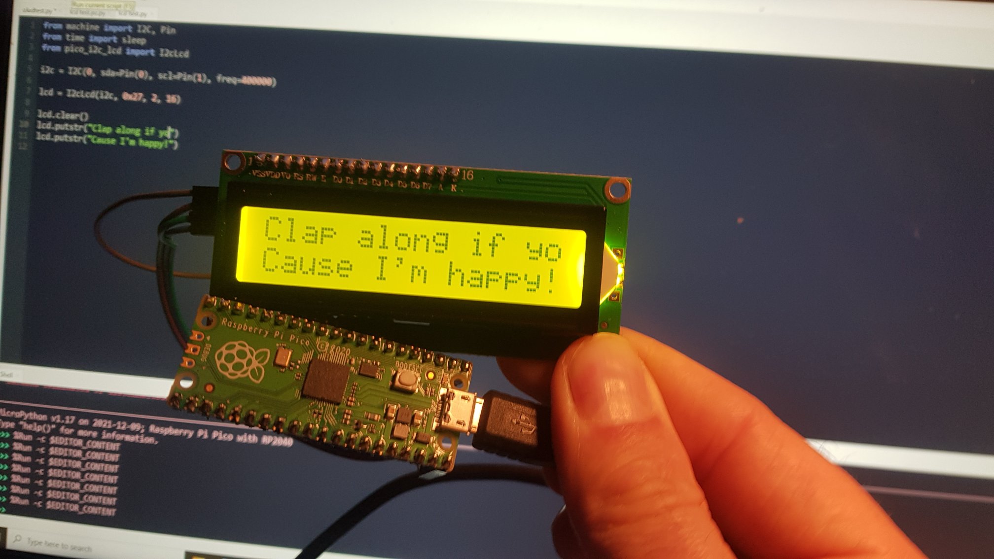
I spent longer than I care to admit on failing to get either a TM1638 LED, an SH1106 OLED or a 1602 LCD to work with my Pico. Turns out one of my jumper wires had an intermittent fault 🤦
After a wire transplant everyone is finally happy!

Kevin the MQTT Owl

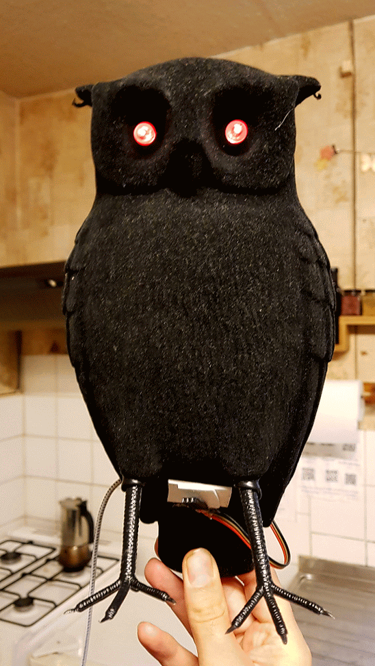
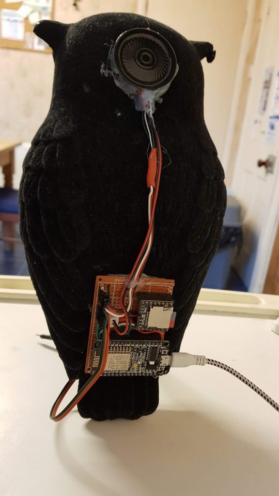
Kevin started his life when my then flatmate found him in a bargain bin for 25p. Once the inbuilt button cell battery had depleted she let me have a play with it.

I removed the battery holder, rewired the eye LEDs, built a circuit board consisting of an ESP8266 and a DFPlayer Mini MP3 Player and hot-glued a speaker where the battery holder used to be.

Initially I simply hooked him up to our doorbell, whose 433MHz signal gets converted into MQTT messages through Sonoff’s RFBridge running the excellent Espurna firmware: